Digital clock |

|
Digital clock |
|
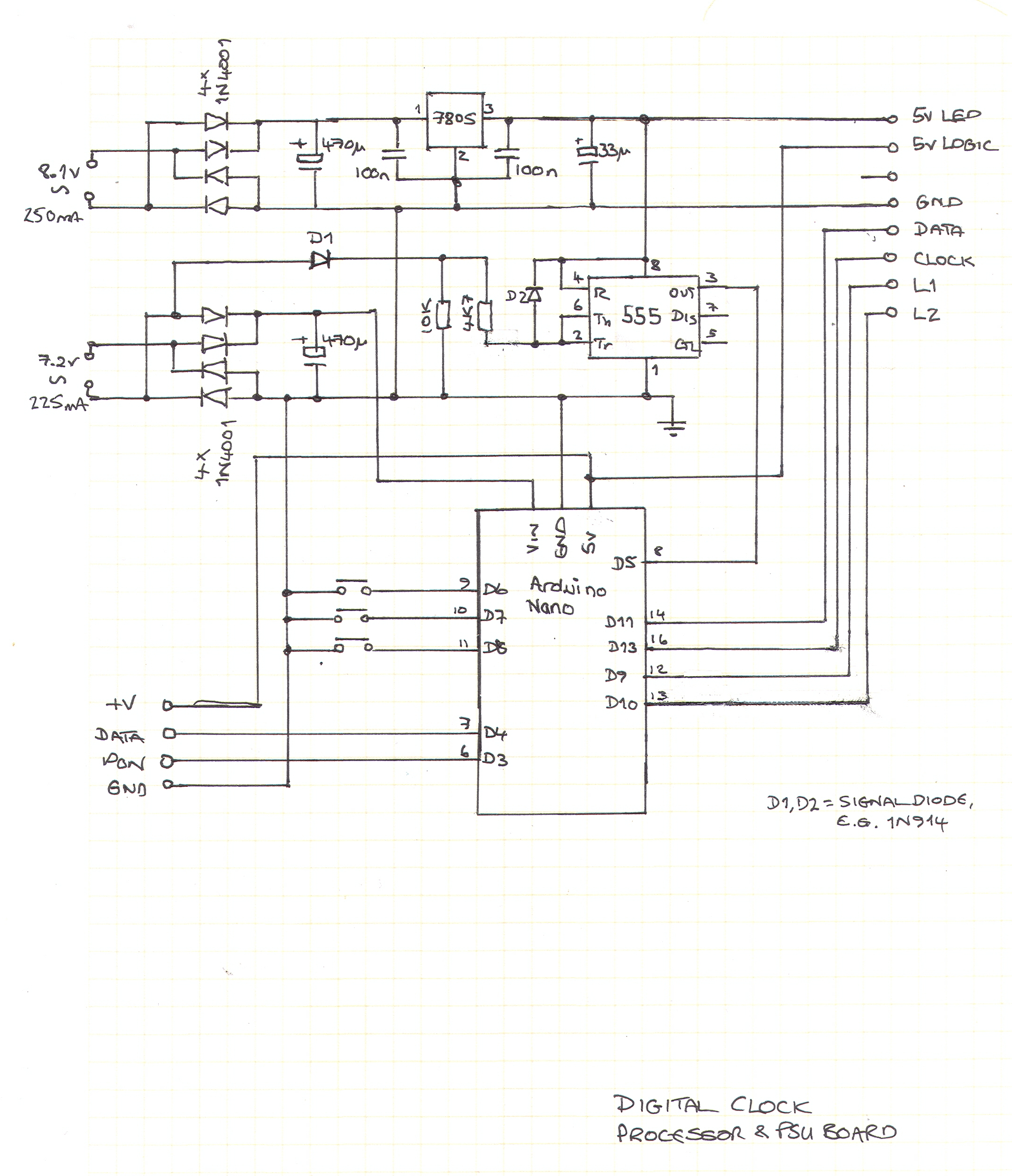
The clock uses an Arduino nano to control the functions. To maintain accuracy it uses a 50Hz signal derived from the mains frequency. The mains frequency in Europe is accurate over long times, although it can drift by up to 20 seconds from UTC in the medium term. For more information, see mainsfrequency.com and the SwissGrid website.
Later there will be an option to synchronize with the DCF77 transmitter at Mainflingen.
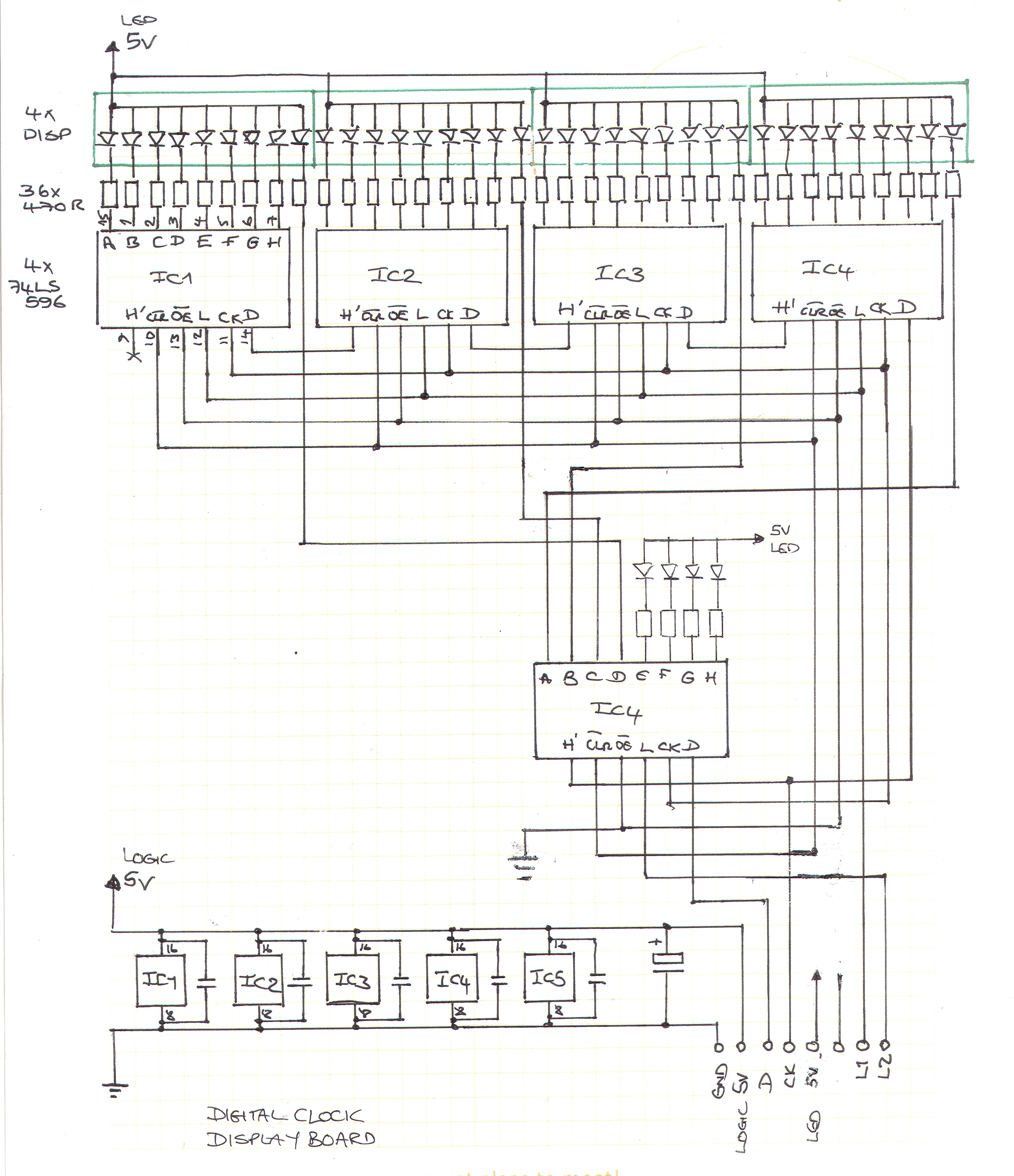
The display board has four separate common anode digits each of which has the normal segments a to g and decimal point, plus an extra point at the lower left side. There's a pair of normal LEDs forming the colon too.
I decided to drive the LEDs directly rather than multiplexing them, so I need 38 pins. To keep the number of connections between the arduino and the display to a minimum, I planned to use five 74HC595 shift registers. Each LED segment needs a driver current of around 5 to 7 mA, so each '595 would have to sink less than 60 mA with all LEDs on - well within its limits. Unfortunately (or fortunately, perhaps) the 74HC595 chips that I ordered (cheap, on ebay) turned out to have open-collector outputs. I'm not sure what they are really (perhaps 74LS596 or 74LS599) and the OE and SRCLR pins don't appear to do anything. Anyway, they do the job, so all's well that ends well.
Four of the shift registers drive the normal segments of the displays. The remaining shift register drives the left-hand points and the colon, with capacity for two more LEDs if they're needed. The shift registers are chained together with a common clock. The odds-and-ends SR is first in the chain and has a separate latch signal, so that I can blink the colon by transmitting a single byte. The four digit SRs have a common latch signal. So there are four control signals from the Arduino to the display board: data (D11), clock (D13) and two latches (D9 and D10).
The total current for the LEDs is around 250 mA when all LEDs are lit. The LED anodes are powered by a separate 5v supply than the logic. The main reason for this is because of the transformer that I used.
The power supply has to be an old-fashioned analogue supply, at least partially, in order to derive a reference frequency from the mains. Getting an encapsulated AC power supply ("wall-wart") these days is quite tricky - most readily available units are switch-mode DC supplies. I found a unit on Pollin that has two secondaries: 8.1v @ 250 mA and 7.2v @ 225 mA. The 8.1v secondary, when rectified and regulated, didn't provide enough current to drive the display and logic. There was an unacceptable ripple, although the clock seemed to work well enough. To remedy that, I decided to supply the LEDs from the regulated supply and the logic on the display board from the Arduino's 5v output. The Arduino's power input (Vin) is supplied by an unregulated 10v or so, derived from the 7.2v secondary. By doing this, even if there's ripple on the LED supply, it won't affect the logic.
To derive the mains frequency, the AC signal from a transformer secondary is routed via a signal diode and 4k7 resistor to the threshold and trigger inputs of a 555 configured as a Schmitt trigger. The cathode of the diode is tied to ground using a 10k resistor to stop it from floating during negative half-cycles. The 555 is powered from the 5v LED rail. To prevent the approx 10v peak signal from causing damage to the 555, the input is clamped to the 5v supply with another signal diode. The output of the 555 is fed to the TCNT1 input (D5) of the Arduino. TCNT1 is used to count the pulses so that no time gets missed, even if the Arduino is busy for more than 40 ms. I consider this preferable to using an interrupt to increment a counter in software; why use software when the hardware can do it for you?
To control the output mode and set the time manually, there are three pushbuttons connected between ground and Arduino pins D6, D7 and D8. The Arduino has internal pull-up resistors, so no other external components are needed.
Finally, the 1Hz data signal from the DCF receiver is connected to an input of the Arduino. One further Arduino pin is used to enable the receiver. The receiver needs a clean reset after power-on and it's easier to use the Arduino than to do it with external components.
Click image for a larger version.
Waiting for project completion.
I'm still looking for a quirky housing for the project; perhaps an old clock case from which the mechanism has already been removed, or a retro radio that I can hack.
I coloured the component side of the display board with a black marker pen and made sure that all the resistors are oriented the same way, so that it looks good even if the whole board is visible in whatever housing I eventually use.
The source code for the project is on GitHub.
|
© David Haworth About this site (Impressum). |

|


|